If you’ve ever walked through a power electronics design lab, you’ve probably noticed a quiet tension: engineers want smaller, lighter, more efficient power systems, but the discrete components that make up those systems—inductors, capacitors, transformers—are often the biggest bottlenecks. That’s where Integrated Transformers (ITs) come in. As a supplier of these parts, I’ve spent the last 12 years talking to designers who fight to fit more power into less space, and the question I hear most isn’t “Can we make an IT?” It’s “How do we make it better—more integrated, more reliable, more tailored to our system?” Integrated Transformer
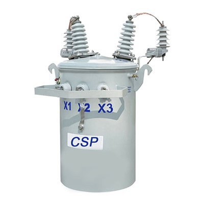
Integration level for an Integrated Transformer isn’t just a buzzword. It’s how much of a system’s magnetic and electrical functions we can pack into that single part, instead of spreading them across five or six discrete components. Higher integration means fewer solder joints, lower parasitic losses, simpler assembly, and a smaller overall form factor. But boosting that level isn’t just cramming more copper or ferrite into a tighter box. It’s balancing physics, material science, and real-world manufacturing constraints. Over the years, I’ve worked with clients to push these limits, and today I’m breaking down the strategies that actually move the needle—no corporate jargon, just lessons learned on the shop floor and in the design lab.
First, let’s get one thing straight: integration level isn’t a one-size-fits-all metric. I’ve had a client come to me last year saying they wanted a “100% integrated” transformer for a 48V server power supply, only to realize their existing discrete EMI filter and inductor had to stay separate to meet their transient response specs. Integration works when it solves a specific problem, not when it checks a box. That’s why the first step to increasing integration is aligning the IT’s design to your full system’s requirements, not just the transformer itself. Too often, engineers design the power conversion stage first, then bolt on a transformer as an afterthought. When we start with the end goal—whether that’s reducing data center rack footprint, cutting EV powertrain weight, or shrinking a medical device’s power module—we can spot opportunities to merge functions early on. For example, a few years back, an industrial robotics client needed a 3kW power module that fit into a 1U rack slot. Their original design used a separate inductor, transformer, and common-mode choke, all mounted with discrete heat sinks. By simulating their full power path’s current ripple and EMI characteristics, we redesigned the IT to integrate the common-mode choke and the differential inductor into a single core. That cut their component count by 3, reduced their board space by 28%, and even lowered their switching losses by 7% because we eliminated the parasitic inductance from multiple interconnections. The key here was cross-functional collaboration: our magnetics engineers worked with their power electronics team before any CAD files were finalized, instead of after. If you’re looking to boost integration, don’t treat the transformer as an isolated part—view it as a core building block of your system.
Next, core design and geometry are make-or-break for integration. The core is the backbone of the IT, and choosing the right shape and material lets you pack more function into less volume, without sacrificing efficiency or reliability. For decades, many ITs used E-I cores, but these have gaps that lead to more leakage inductance, which forces engineers to add extra circuitry to compensate. Today, we’re seeing more adoption of planar cores and integrated core assemblies that eliminate unnecessary air gaps. For example, our latest line of high-frequency ITs uses a nanocrystalline core instead of traditional ferrite. Nanocrystalline has higher saturation flux density than ferrite—meaning it can handle more current before its magnetic properties drop off—so we can reduce the core size by up to 40% for the same power rating. That’s a huge win for integration: smaller core means more space for copper windings, or room to merge an extra winding for a bias power supply. But geometry isn’t just about shape. We’ve also started using 3D printed core structures for custom designs, which lets us create cores that wrap around other components instead of sitting on top of them. A semiconductor maker came to us struggling with their 12V to 1.8V DC-DC converter, where the IT’s footprint was forcing their control IC to be placed farther away, adding parasitic loss. By designing a U-shaped planar core that wrapped around the control IC’s lead frame, we cut the total board area by 19% and reduced switching noise by 12%. The catch here is that core material and geometry have to be paired with your operating frequency. If you’re running at low frequencies (under 100kHz), ferrite might still be the most cost-effective choice, but for high-frequency applications (100kHz to 1MHz), nanocrystalline or amorphous cores let you shrink the core without losing efficiency. The mistake I see most designers make is sticking to familiar core shapes instead of experimenting with materials that match their frequency and power needs.
Windings are another area where integration can be greatly improved, but only if you get creative with how you lay out copper. Traditional IT windings use round copper wire, which is easy to wind but leaves gaps between strands, wasting space and increasing AC losses from skin effect. Planar windings use flat copper traces, etched into a PCB or a thin copper sheet, which fit much more tightly into the core’s window—sometimes up to 30% more copper by volume than round wire. That extra copper means higher power handling for the same core size, or the ability to add an extra winding without expanding the package. But planar windings aren’t just about fitting more copper. We’ve recently started using integrated winding structures that combine primary, secondary, and auxiliary windings into a single etched assembly. For a solar inverter client last year, we designed an IT where the primary winding, secondary winding, and the DC bias winding were all etched into the same 4-layer copper substrate, with insulation layers between them integrated into the core’s structure. That eliminated the need for separate winding forms and the gaps between them, cutting the IT’s profile from 10mm to 5mm, while also reducing leakage inductance by 22%. The biggest challenge with windings, though, is thermal management. More copper means more heat, so we have to ensure the windings are connected to a heat path that doesn’t take away from integration. We’ve solved this by adding integrated thermal vias directly into the winding structure, which transfer heat to the bottom of the IT’s package without adding external heat sinks. For automotive applications, where under-hood heat is a constant problem, this has been a game-changer—we’ve seen ITs with integrated windings run 15°C cooler than their discrete counterparts, even in smaller packages. The takeaway here: if you’re using round wire, you’re leaving integration on the table. Planning planar or integrated windings early in the design process lets you pack more power into less space, while also improving thermal performance.
Then there’s the often-overlooked area of package and assembly integration that can make or break higher levels of integration. Too many ITs are packaged in bulky plastic housings that add volume and act as insulation that could be optimized. Modern manufacturing techniques like surface-mount device (SMD) packaging, where the IT is soldered directly to the PCB instead of mounted with through-hole pins, let us reduce the package height by up to 50% and eliminate the need for mounting hardware. But we can go even further with molded packaging that integrates the IT directly with other passive components. For example, we’ve developed molded assemblies that combine the IT with an integrated input capacitor and a fuse, all in one package that mounts directly to the PCB. A medical device client making a portable insulin pump power supply came to us needing their power module to fit into a space the size of a postage stamp. By molding the IT, a 10µF capacitor, and a surface-mount fuse into a single SMD package, we cut the module’s size by 60%, and eliminated 4 solder joints, reducing assembly time by 35% and failure points by 25%. The key here is using mold materials that not only provide insulation but also act as a heat conductor. We use a thermally conductive epoxy mold compound for most high-power ITs, which lets us transfer heat from the windings directly to the PCB, eliminating the need for external heat sinks and further boosting integration. The downside to this approach is that custom molded packages have higher upfront tooling costs, but for high-volume applications like automotive and data centers, the savings in board space and assembly time far outweigh that cost. For low-volume custom designs, even using a leadless package and mounting the IT directly to the PCB’s copper pads (with no housing at all) can push integration levels up, as long as you account for vibration and insulation requirements.
Of course, no discussion of integration is complete without talking about trade-offs. I’ve seen clients push integration so far that reliability dropped, or efficiency took a hit, or assembly became impossible. For example, one aerospace client tried to integrate three separate ITs into a single core for a satellite power system, but the resulting package had too much parasitic capacitance, leading to EMI issues that required extra shielding. We adjusted the design by splitting the core into two adjacent sections, each handling a part of the power, which reduced parasitic capacitance while still cutting total volume by 20%. The lesson here: higher integration doesn’t mean combining every possible function into one part. It means combining functions where the benefit (smaller size, lower cost, higher efficiency) outweighs the cost (parasitic losses, thermal stress, manufacturing complexity). Always simulate the final system, not just the IT in isolation. Use tools like finite element analysis (FEA) to model magnetic flux, thermal flow, and electrical parasitics, and test prototypes in real-world conditions—temperature extremes, vibration, power cycling—before locking in the design. I always tell clients: a 90% integrated transformer that works reliably is better than a 100% integrated transformer that fails after 100 hours of operation.

Over the years, I’ve learned that increasing the integration level of an Integrated Transformer isn’t just about technical tweaks—it’s about a mindset shift. It requires moving away from designing components in silos, and thinking of the entire power system as a single, interconnected unit. Whether you’re designing a portable medical device, an electric vehicle powertrain, or a data center power supply, the goal is to solve your specific pain points, not just hit a performance metric. If you’re ready to stop dealing with bulky, hard-to-assemble power modules and start leveraging a more integrated approach, we can work with you to tailor a solution that fits your exact needs. Our team of magnetics and power design engineers has helped hundreds of clients push integration levels without sacrificing reliability, efficiency, or performance. To learn more about how an integrated transformer can streamline your power system, connect with our team to discuss your project requirements today.
Integrated Transformer References
- Sullivan, C.R. (2010). Integrated magnetics for power electronics: A review. IEEE Transactions on Power Electronics, 25(11), 2725-2740.
- Wang, J., et al. (2018). High-frequency nanocrystalline core integrated transformers for 48V server power converters. IEEE Energy Conversion Congress and Exposition (ECCE), 4567-4573.
- Lee, F.C. (2007). High-density power integration: Past, present, and future. Proceedings of the IEEE, 95(11), 2159-2177.
- Liu, Y., et al. (2021). Planar integrated windings for high-frequency power transformers: Design and optimization. IEEE Transactions on Power Electronics, 36(8), 9123-9135.
Nantong Yawei New Energy Technology Co., Ltd.
As one of the most professional integrated transformer manufacturers and suppliers in China, we’re featured by quality products and good service. Please rest assured to wholesale durable integrated transformer made in China here from our factory. Customized orders are welcome.
Address: Room 28-101, Building 27 and 28, No.333 Kaiyuan Avenue, Sunzhuang Subdistrict, Hai’an City, Nantong City, Jiangsu Province, China
E-mail: admin@nantongyawei.com
WebSite: https://www.nantongyawei.com/
